In order to create holes and opening, some rules must be followed. We classify components into 2 groups, cylindrical and non-cylindrical..
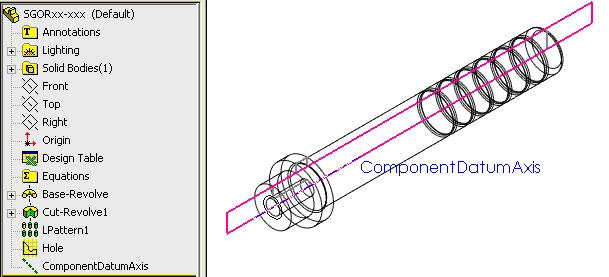
The holes for cylindrical components are created by revolving a sketch.
User can define their own component, the rule is simple –:
A reference axis named ComponentDatumAxis must be created
A sketch named as Hole to revolve cut the hole
Front plane is by default use to define distance mating during component insertion
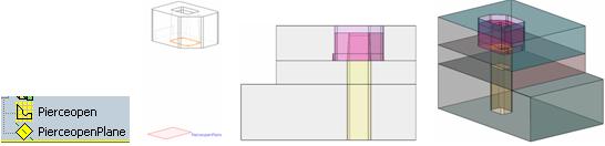
Holes for non-cylindrical components are created by subtraction or extrude cut.
For Boolean type holes, 3DQuickPress will use all the bodies in the part doc and the plate is subtracted by the bodies. If you have special hole, create a body for the hole.
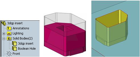 Hole created
For Extrude cut, create a plane for end condition and a sketch. You can create multiple pairs for different clearances, but only one sketch is use to create hole in Component Opening. The plane must be named as “Sketch name”+”Plane”